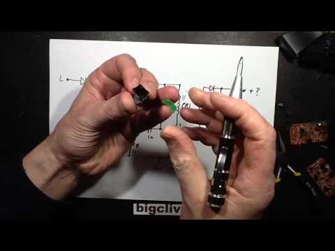
Well that’s me destroyed ALL the power supplies that came with the meteor lights now, and now I do actually understand the feedback technique. It took a very careful and slow unwinding of the last transformer to note the direction of the windings to make sense.
So basically speaking, the feedback winding has two purposes. When the transistor is on it provides positive feedback to its base to drive it on until the core saturates and no more current can be coupled across. Then when the transistor turns off, the feedback winding mimics the secondary by detecting the maximum voltage reached as the secondary charges its capacitor with the current induced by the collapsing field.
The feedback winding uses that (negative) current to charge its capacitor via a diode negative with respect to the transistors emitter (0v) and when the voltage being mirrored on the feedback capacitor reaches the desired level the transistors drive circuit has to overcome the zener voltage which effectively puts the transistor into a low level standby mode. Still running, but not at full tilt.

