more at
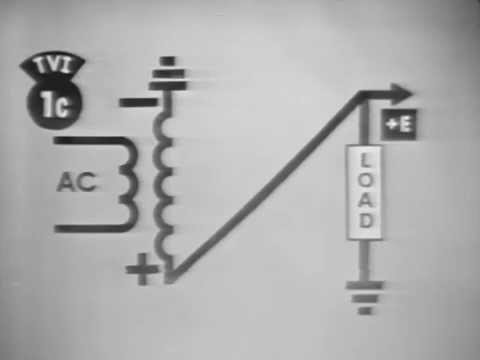
“The development of the bridge rectifier is traced by showing how the output voltage is affected by the various rectifier configurations. all components are identified and labeled. current flow is traced and the output waveshape is shown using the trainer and oscilloscope and probable troubles causing these symptoms are discussed.”
NEW VERSION with improved video & sound:
US Air Force Training Film TVK 30-236, Air Training Command.
Electronics training playlist:
Public domain film from the US National Archives, slightly cropped to remove uneven edges, with the aspect ratio corrected, and mild video noise reduction applied.
The soundtrack was also processed with volume normalization, noise reduction, clipping reduction, and/or equalization (the resulting sound, though not perfect, is far less noisy than the original).
Wikipedia license:
A diode bridge is an arrangement of four (or more) diodes in a bridge circuit configuration that provides the same polarity of output for either polarity of input.
When used in its most common application, for conversion of an alternating current (AC) input into a direct current (DC) output, it is known as a bridge rectifier. A bridge rectifier provides full-wave rectification from a two-wire AC input, resulting in lower cost and weight as compared to a rectifier with a 3-wire input from a transformer with a center-tapped secondary winding.
The essential feature of a diode bridge is that the polarity of the output is the same regardless of the polarity at the input. The diode bridge circuit was invented by Polish electrotechnician Karol Pollak and patent was recorded in 14 Jan, 1896 under the number DRP 96564. It was later published in Elektronische Zeitung, vol. 25 in 1897 with annotation that German physicist Leo Graetz also was researching this matter at that time. Today the circuit is still often referred as Graetz circuit or Graetz bridge…
… this circuit not only produces a DC output from an AC input, it can also provide what is sometimes called “reverse polarity protection”. That is, it permits normal functioning of DC-powered equipment when batteries have been installed backwards, or when the leads (wires) from a DC power source have been reversed, and protects the equipment from potential damage caused by reverse polarity.
Prior to the availability of integrated circuits, a bridge rectifier was constructed from “discrete components”, i.e., separate diodes. Since about 1950, a single four-terminal component containing the four diodes connected in a bridge configuration became a standard commercial component and is now available with various voltage and current ratings.
Output smoothing
For many applications, especially with single phase AC where the full-wave bridge serves to convert an AC input into a DC output, the addition of a capacitor may be desired because the bridge alone supplies an output of pulsed DC…
The function of this capacitor, known as a reservoir capacitor (or smoothing capacitor) is to lessen the variation in (or ‘smooth’) the rectified AC output voltage waveform from the bridge. There is still some variation, known as ripple…
The simplified circuit shown has a well-deserved reputation for being dangerous, because, in some applications, the capacitor can retain a lethal charge after the AC power source is removed. If supplying a dangerous voltage, a practical circuit should include a reliable way to discharge the capacitor safely. If the normal load cannot be guaranteed to perform this function, perhaps because it can be disconnected, the circuit should include a bleeder resistor connected as close as practical across the capacitor….
The capacitor and the load resistance have a typical time constant τ = RC where C and R are the capacitance and load resistance respectively. As long as the load resistor is large enough so that this time constant is much longer than the time of one ripple cycle, the above configuration will produce a smoothed DC voltage across the load….
In older times], this crude power supply was often followed by passive filters (capacitors plus resistors and inductors) to reduce the ripple further. When an inductor is used this way it is often called a choke. The choke tends to keep the current (rather than the voltage) more constant. Although the inductor gives the best performance, usually the resistor is chosen for cost reasons.
Because of the increasing availability of voltage-regulator chips, passive filters are less commonly used. The chips can compensate for changes in input voltage and load current, which the passive filter does not, and eliminate ripple to a high degree…
